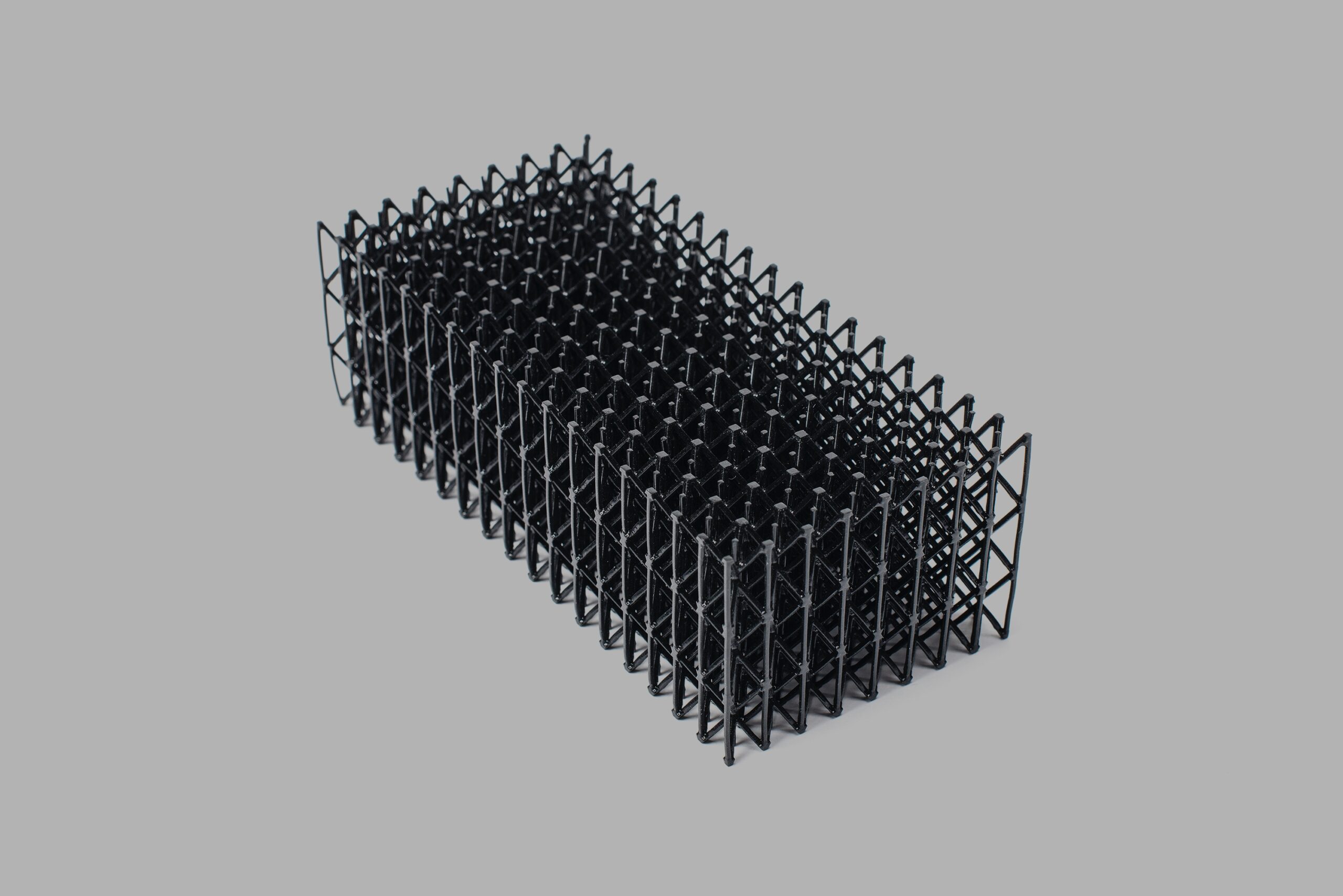
With the growth of additive manufacturing, there has been a lot of buzz around lattices — structures composed of repeating unit cells. Previously impossible to manufacture, lattices can now be leveraged for functions such as lightweighting, foam replacement, enhanced heat transfer, aesthetics, and noise- and shock-absorption.
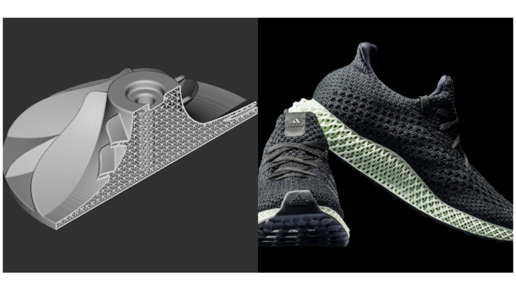
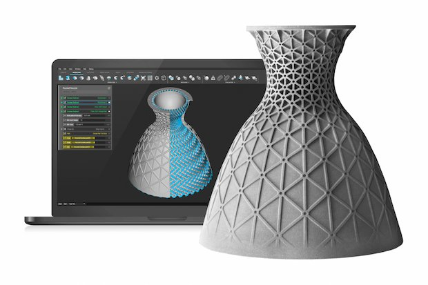
Having a machine capable of manufacturing lattices is of little use without a powerful software capable of designing them. Luckily, there has been a lot of innovation in the advanced modeling space. One company making new things possible is nTopology. Here are a few of the ways that their software nTop Platform can level up your latticing workflow.
Computing model and interface
nTop’s user interface and computational model contain a lot of features that make the software very efficient. To begin, they represent geometry “implicitly” rather than parametrically. Whereas parametric models are built up using geometric features, constraints, and relations, implicit models are represented by a continuous, three-dimensional mathematical field, and subsequent CAD operations are executed by making changes to its representative function. This allows you to quickly and easily create complex geometry.
Additionally, the files are extremely lightweight, meaning they compute and render quickly. Furthermore, it is impossible to have rebuild errors after changing features “upstream” since each operation is just a modification of the equation representing its input. Parametric models, by contrast, are easy to “break” when changes upstream cause later features to have missing constraints or reference features.
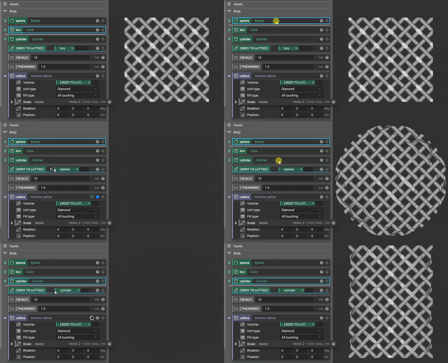
The interface also allows you to define your own variables and create custom blocks to easily modify your model and even package up workflows and apply them to other parts and files. For example, if I am making the same design in multiple sizes, I can simply swap out the base part and it will reapply all the subsequent operations to that new part. I could also create a custom block that just shows the key parameters and generates a prescribed output. If I had to lattice a million similar parts, I might even write a python script to automate batch processing.
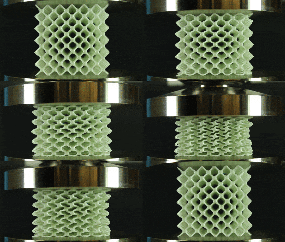
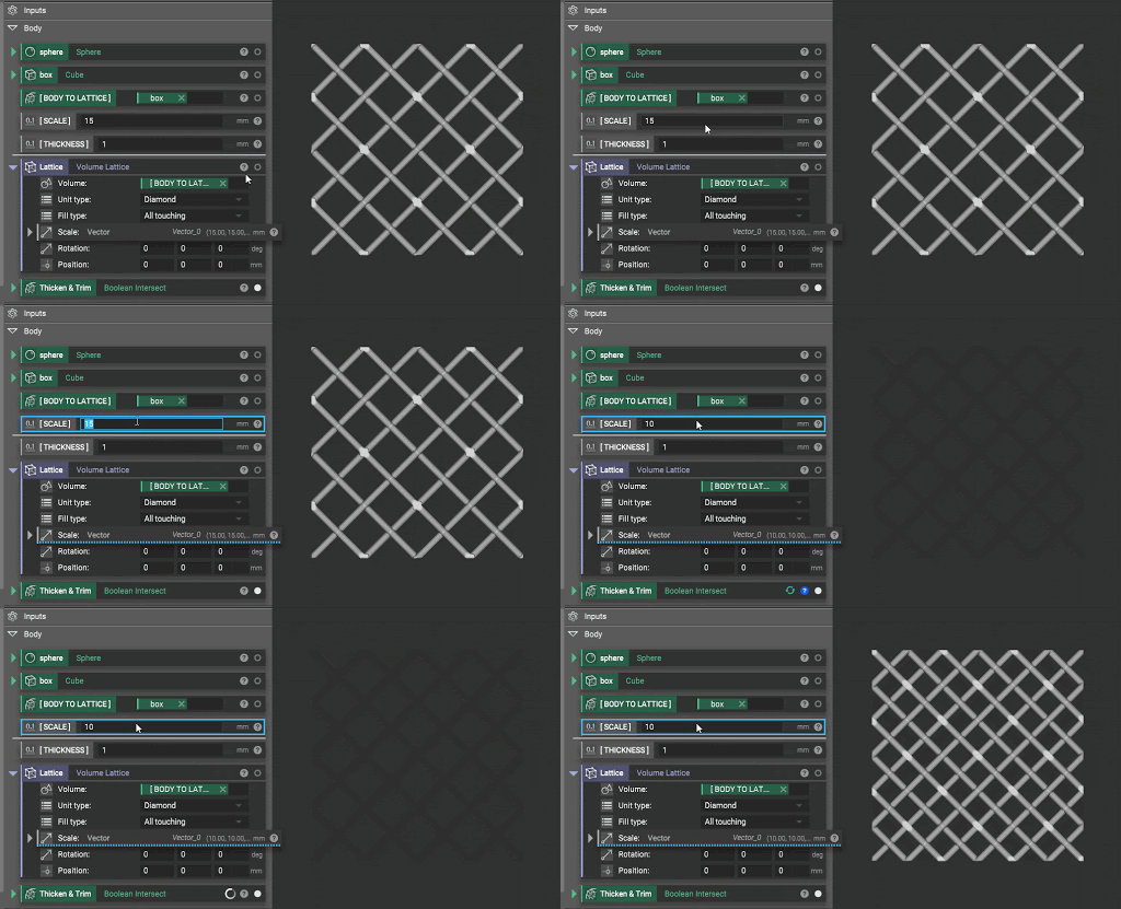
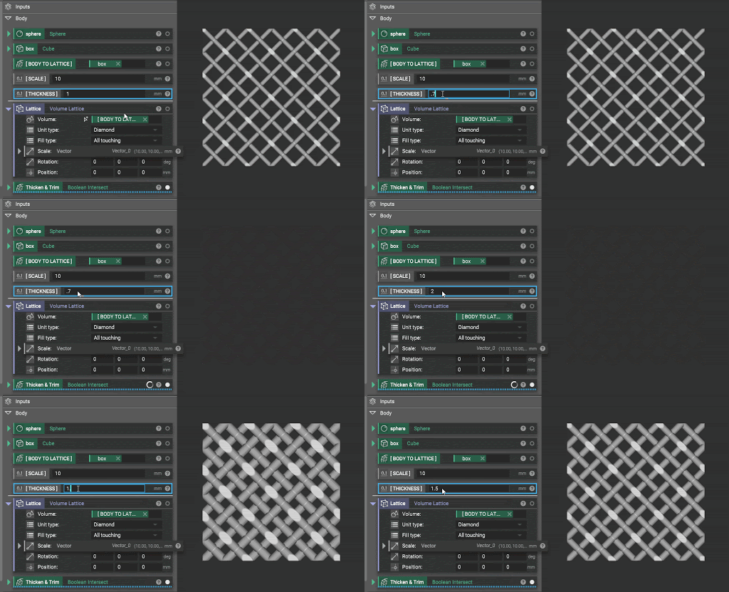
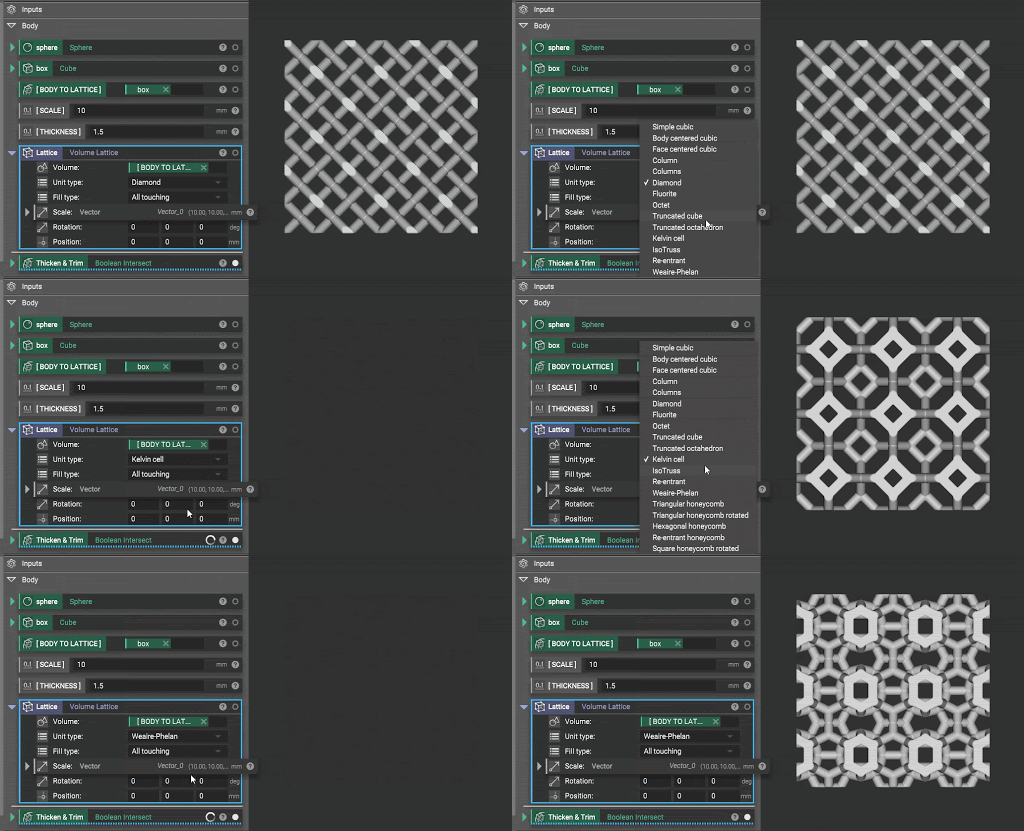
This agility is particularly useful when latticing; for novices and experienced latticers alike, it can take some experimentation and fine-tuning to dial in lattices for printability and functionality. The animations below demonstrate how fast it is to change different parameters of your lattice.
Additionally, if you make a change to the base CAD in your other modeling programs, you can drop in the new part and the entire workflow is reapplied to the revised geometry. This allows you to move quickly and focus on the design rather than rebuilding your model with every iteration.
Field-driven design
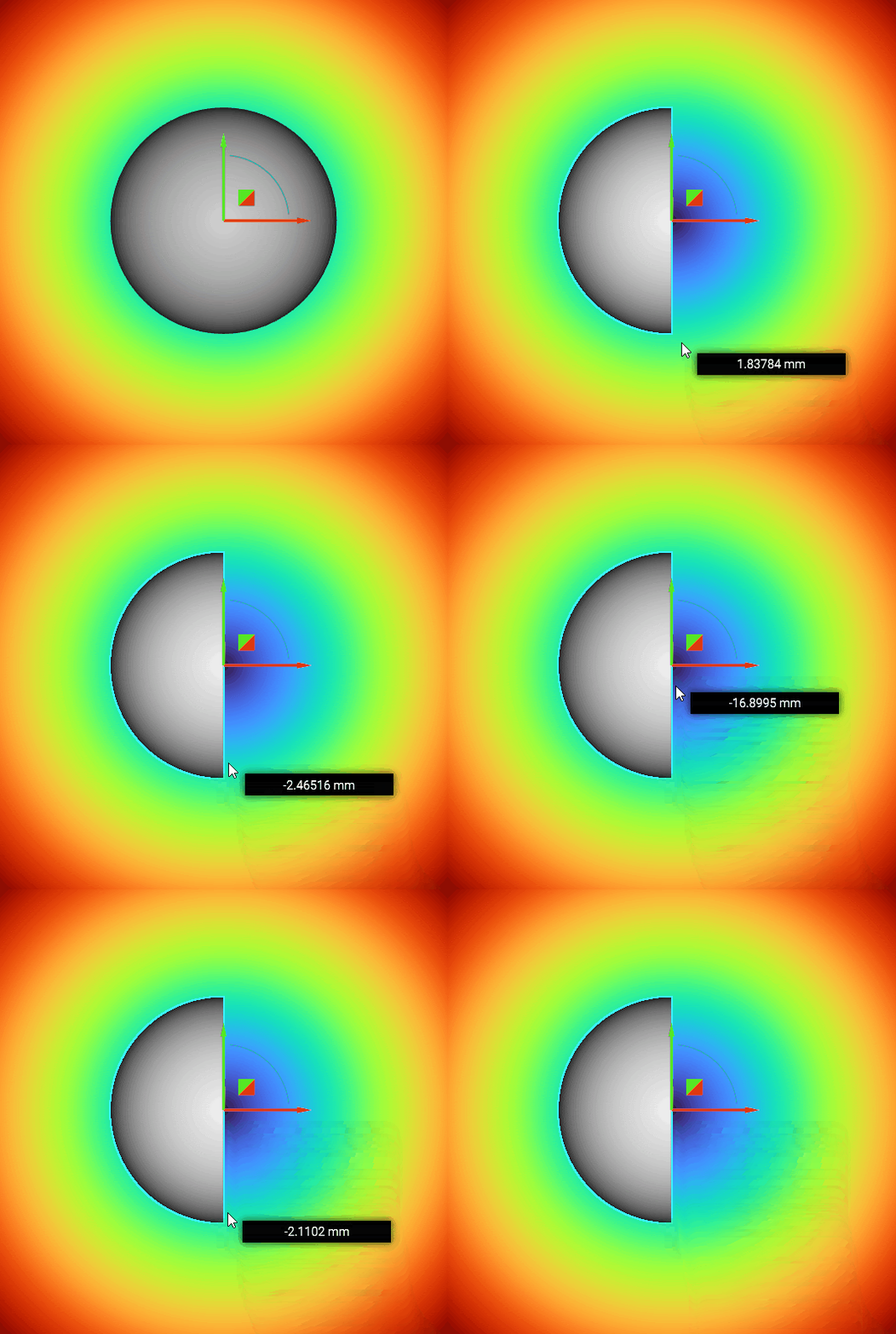
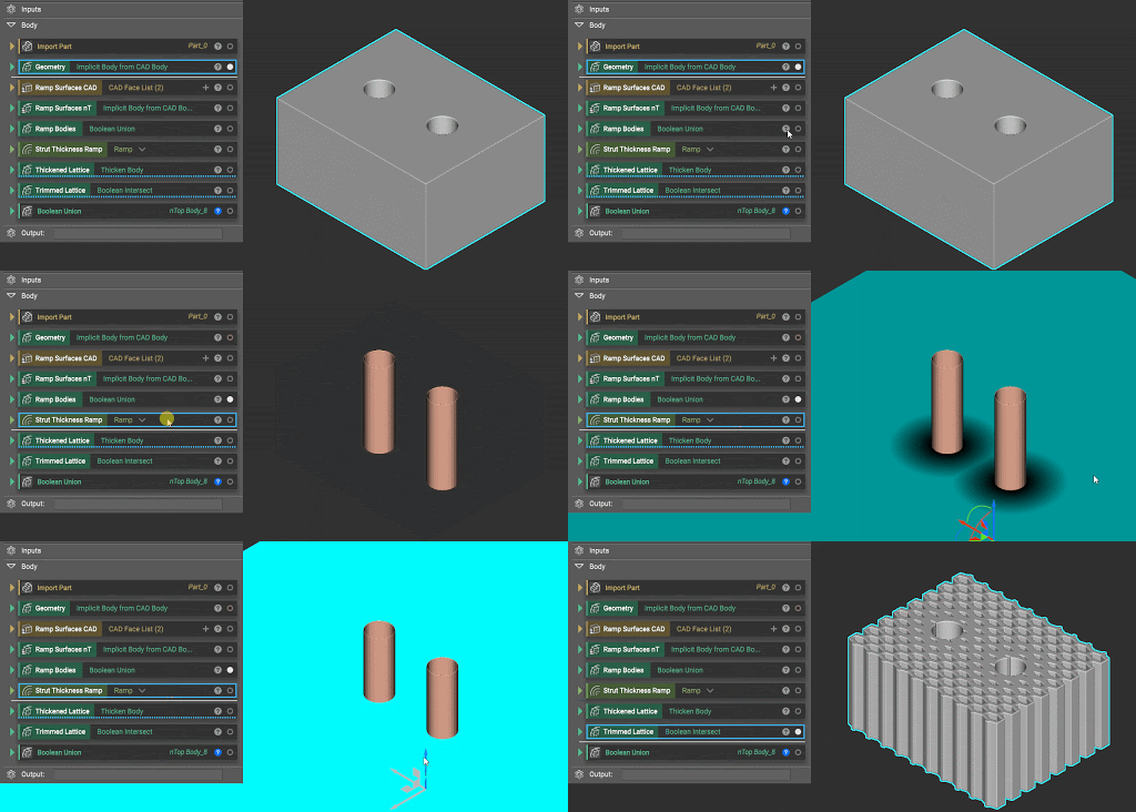
Another powerful feature in nTop is the ability to manipulate geometry using data such as other geometry, imported data, or simulation results. Take this block with two holes in it. To reinforce those holes, you can select the faces of the holes to ramp the lattice beam thickness such that it is thicker at those faces and clamped to a minimum thickness at a set distance from the holes.
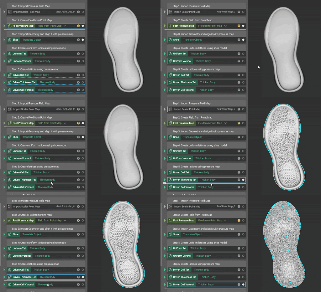
It is also possible to import data sets to drive geometry. In this example, a pressure map of a foot is imported as a point map that is used to either increase the beam thickness at points of high pressure or increase unit cell density. The software also has built-in capabilities for finite element analysis (FEA) that allow you to generate simulation data that can then feed back in and drive your design. By moving from simulation-informed design to simulation-driven design, engineers can increase the speed at which they design as well as produce better performing parts. For example, the workflow below enables mass-customization of shoe midsoles; importing custom pressure maps rapidly generates unique latticed insoles to maximize comfort.
These examples only scratch the surface of the power of nTop. Here at Fast Radius, we have a team of nTop experts, and would love to help you discover the power of advanced modeling software for your applications. Contact us to get started.
Interested in learning more about lattices and computational engineering? Visit our resource center for articles on lattice design considerations, mechanical properties, mechanical responses, and tips for generative design.
